Project summary
Over the last couple months I’ve been gaining experience machining parts using the CNC mill. This has involved programming tool paths in Fusion, experimenting with different fixturing setups, and getting acquainted with the Tormach PCNC 440 we have in our makerspace. This post covers some of the parts I’ve made and the challenges I encountered.
Summary of Parts
There are three parts I helped make from scratch: the front lower suspension brackets, the linear rod mounts, and the rack mount in the steering system. There was also a part, the front shock mount, that I didn’t make from scratch but needed the CNC to modify. I think it’s the most interesting part I made of the four so I will cover it in more detail.
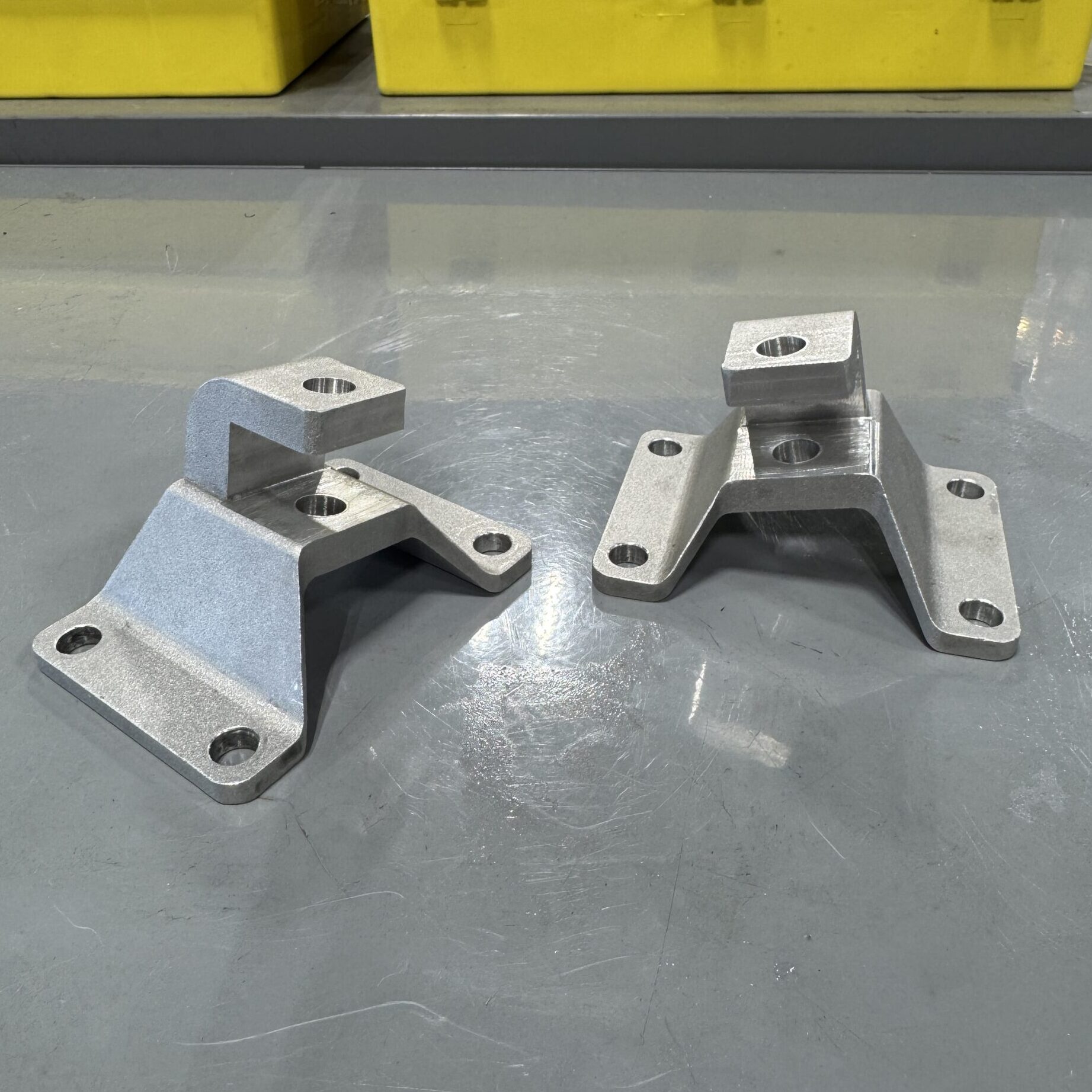
The shock mount, front lower suspension bracket, rack mount, and linear rod mount are shown below in context of the front left suspension and steering systems, respectively.


Below are photos of how the linear rod mount, suspension bracket, and rack mount turned out.


Shock Mount
The shock mount was an interesting part because it was only possible to get 5-axis CNC quotes for it, which would’ve been prohibitively expensive. So we decided to 3D print (out of aluminum alloy) a simplified version of the part that didn’t include the pocket and shoulder bolt hole, and to then try to machine the critical features ourselves.

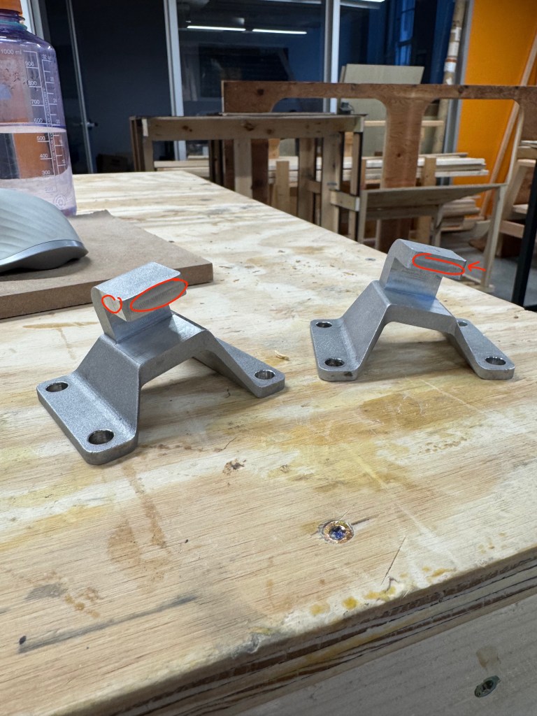
The critical features of the part are the pocket and bolt hole (circled above). We need these features to have the same position relative to the bolt holes as in the CAD, as the bolt holes ultimately determine how the shock mount is located relative to the chassis and thus the rest of the suspension components.
I came up with the plan to make a custom fixture with machined probing surfaces. The shock mount would be mounted to the fixture via the bolt holes, and the bolt holes would be located using the same surfaces that would be used to locate the pocket and shoulder bolt hole for the CNC.


The fixture was machined on the manual mill due to size constraints on the CNC. The bolt holes were located by probing off surfaces 1 and 2. The same surfaces would act as the probing points for the CNC, ensuring the bolt holes and the critical features are located off the same datums, and thus located correctly relative to each other.

The CNCing consisted of two operations: the first to mill out the pocket, and the second to mill reference surfaces (highlighted above) to then be used for drilling/reaming the shoulder bolt holes (we again couldn’t do this on the CNC due to size constraints). I encountered an issue milling the reference surfaces in that milling according to the CAD wasn’t removing any material, so I had to negative offset the surfaces by a few hundredths of an inch in order actually make a machined surface. I elaborate more on that here.
I was able to record some of the pocket operation by taping my phone to the inside of the enclosure. I think it turned out great!
In order to drill and ream the shoulder bolt holes, I needed to make custom angled parallels so the hole would be oriented perpendicular to the top surface.


The final result came out really nice. The shocks fit perfectly and the other suspension components interfaced with it exactly as intended. With this, we were able to integrate the full front suspension and steering rack onto the mockup chassis.
