Project summary
This was the final project in my electromechanical systems class. For phase one of the project, my partner and I were tasked with making an “intrepid” robot that could drive up a steep ramp. For phase two, the task was to have the robot work together with another robot to autonomously push a long tube up both of our ramps. For hardware fabrication we mostly laser cut and 3D printed parts designed in Onshape, additionally employing bearings, buttons, PVC, and dowels. For software, we used a Flask web server on a Raspberry Pi to communicate wirelessly with both the controller Laptop and another robot.
Phase One
How I did It
The first decision we had to make was how the robot was going to move. We settled on a simple two-wheel, direct-drive differential steering system with a back castor ball. This design was simple, enabled the robot to turn, and was convenient since we had two low RPM, high torque motors on hand.
With the basic idea in mind, we began drawing up our design in Onshape. We decided to center the design around a laser-cut acrylic plate, since it would enable accurate placement of parts, easy reproducibility, and high modularity.

We then designed the various parts that would be fastened to the plate via hex screws. This included the two motor mounts and castor mount. For this step, we had to make sure the wheels and the castor would be level when contacting the ground. We also needed to design a part that would fix the wheels to the motor shaft.


After adding some extra mounting holes for a Raspberry Pi and L289N motor controller, we then fabricated the parts with 3D printing and laser cutting. We used threaded heat set inserts for the 3D printed parts to provide a strong connection with the plate. In general, we aimed to minimize the amount of temporary fastening methods (e.g. tape, hot glue) we used, but we eventually had to make compromises due to the short time frame of the project. For example, we used tape to attach the 5V and 12V batteries that powered the Pi and motors, respectively. We improved this during phase two, however.


Results
The robot could easily climb up the ramp (as seen in the video) and also maneuver around quite easily thanks to the differential steering. The wireless communication and WASD keyboard controls made it really fun to just drive around. We would soon discover, however, that the phase two tasks would require us to make a lot of modifications.
Phase Two
How I did it
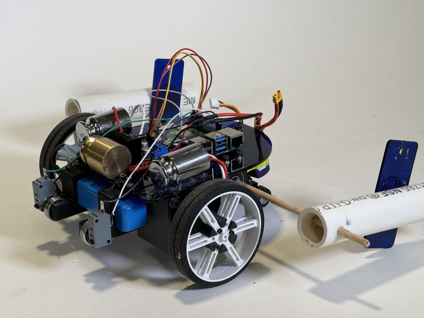
For phase two, we modified the bot so it was more well-equipped to the task of pushing a tube up a ramp. We improved the design by lengthening the main plate to provide more space, adding pieces to securely fasten the 5V battery, and doubling the wheels for added stability. In order to more smoothly push the tube up the ramp, we also designed the battery holder to seat bearings that would contact the tube and roll as the tube rolls.


With this in place, the bot was ready to test. It had traction issues, so we glued 200g weights on top of the wheels to provide greater static friction with the ramp. The metal castor ball from before was also scraping the ramp surface instead of rolling, so we opted to swap it out for a lego wheel. It would mean that the robot couldn’t turn as easily, but since most of the weight was on the front wheels, this wasn’t significant.
Another issue was that the robot was to ascend the ramp after a single user start command; it couldn’t receive constant input from the user like in phase one. So we needed to devise a way to keep it centered on the ramp. Getting inspiration from other teams, we decided on a mechanism with two acrylic stabilizers on either side that slide along the outer sides of the ramp, fixed to a dowel that’s free to rotate behind the front wheels.

The idea was that the robot could drive freely on flat surfaces without the influence of the stabilizers, and then when the robot attempts going up the ramp, the stabilizers would drop down and kick into action. The stabilizers initially weren’t heavy enough to resist the robot veering off center, so we added PVC tubes.
In the video below the robot manages to push up a partial tube by itself with one initial starting command. You can see the stabilizers dropping down as the robot gains enough height.
Solo ramp ascent
Now that we knew the robot could ascend the ramp by itself, we needed to address the part of the task that involved working collaboratively with another robot. To do this, we needed a way to match the speed of the other robot. Before running the robots, our team and the other would have them agree on a starting speed, and then they would have to somehow match each other thereafter.
Our solution to this was using two buttons attached at the front, which would inform the robot if the robot was going too fast or too slow. The logic is as follows: If both buttons were being pressed, the tube is level and both robots are going at the same speed. If the bot is on the left ramp and the left button is pressed but the right button isn’t, it means the robot is going too slow. If the bot is on the right ramp and the left button isn’t pressed but the right button is, then the robot is going too fast. The opposite cases are true for if the robot is on the right ramp. Using this information, the robot can make constant autonomous speed adjustments to match the speed of the partner bot.
The buttons are visible in the featured image:

With these additions, and a lot of code, the robot was ready to tackle the intended goal of collaborating with another robot to push a tube up the ramp.
Here is a video summarizing the features of the updated robot:
Results
On demonstration day it was a great success! It worked with all the robots we tried with.
In the video below you can see the speed adjustment system in action. Our robot initially gets off to a quicker start and the tube starts tilting so it slows down. When the other robot speeds up and the tube starts tilting the other way, ours speeds up to match it.