Project Summary
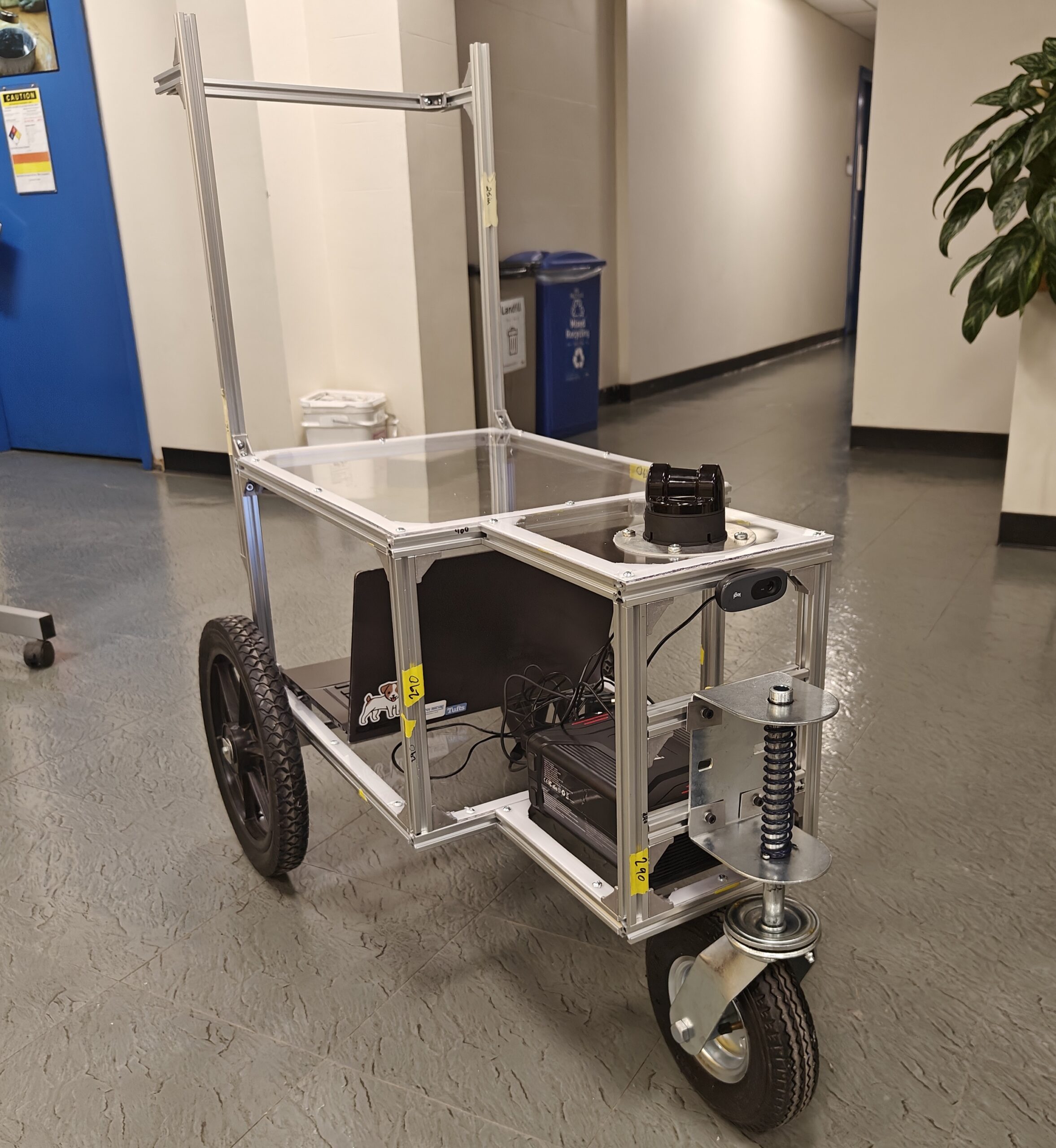
My senior design project, sponsored by the DOT Volpe Center, was to design and fabricate a pedestrian activity data collection unit used to train self-driving car algorithms. My two other team members and I ended up settling on a push cart concept, with room for a laptop and battery, and the lidar and cameras mounted on the end opposite the person pushing.
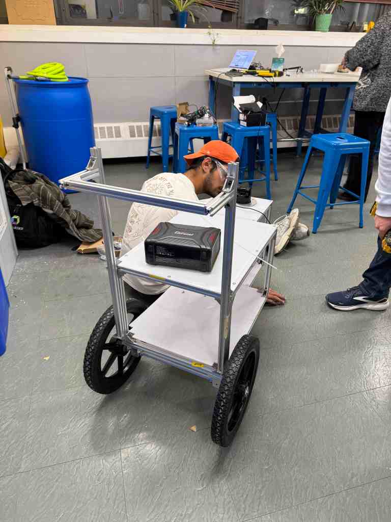
We made two prototypes. The first was a wooden frame mounted atop a store-bought garden cart. The second was a scratch-built aluminum t-slot frame with a custom wheel assembly design. I led the design and fabrication of both.
I am very proud of the final result, as we largely met the user needs we identified. I also learned a great deal about the entire engineering design process from concept to completion.
Skills Involved
- Rapid prototyping
- CAD/FEA
- Frame, wheel, enclosure design
- Lathe/Mill
Background
Currently, most data for training autonomous driving algorithms is collected via car-mounted sensor suites and stationary units mounted at intersections. The advantage to a small, movable data collection unit is that it can collect data in tight pedestrian spaces, enlarging the training data set.
The two main applications of lidar to autonomous driving are localization (determining position of vehicle relative to static surroundings) and detection (recognizing and classifying the objects surrounding the vehicle). Even if the data collected by such a device is not relevant to localization specifically for cars, it can definitely be relevant to localization of smaller vehicles that travel over pedestrian infrastructure, such as small autonomous delivery robots.

Prototype 1
For both prototype 1 and 2, we generally followed the design spiral, which consists of:
- Identifying user needs
- Defining engineering specifications
- Generating concepts
- Evaluating concepts
- Making detailed designs
- Building and testing

User Needs
The first step was identifying the needs of our client. We ended up identifying data quality, portability, ease of use, durability, and safety as our client’s most important needs.
Data quality specifically means minimizing vibration and obstruction, which are critical to the proper functioning of a lidar sensor.
Portability was important because the device needed to be easily transportable in the trunk of a car. It also shouldn’t be overly cumbersome to move around in general.
Ease of use was important because the cart needed to be easy to setup and push and comfortable to use for long periods of time.
Durability was important because the cart needed to be able to withstand harsh outdoor environments and driving over real sidewalks and roads, and to protect expensive electronics from rain and debris.
Safety is of course important for any physical device. We needed to make sure our unit was safe for both the operator and for other people on the road.
Engineering Specifications
We didn’t spend much time defining engineering specifications for the first prototype, since it was to be just a rough mock-up. But we knew it should be easily portable, comfortable to push, and have enough space to house and mount all the required electronics.
I did do some basic trig calculations to find the maximum vibration amplitude we could tolerate without compromising the quality of the lidar data, which we found to be 8 mm.
Generating Concepts
We came up with 5 concepts for the first prototype, 4 of which were a pushable device on wheels of some kind, and 1 was a backpack.


Evaluating Concepts
In order to help us decide which concept we should go with, we used a decision matrix.

First of all, the decision matrix revealed that a backpack design was not a good idea, since it performs poorly relative to a cart in terms of comfort (part of ease of use), minimizing vibrations (part of data quality). Next, we found that the lawnmower-style concept 2 could be ruled out because it would have difficulty isolating vibrations, would likely be less durable, and also less easy to use due to its low height to the ground. Concepts 1, 3, and 4 were all similar designs. Concepts 3 and 4 were newer and had more fleshed out features, so we knew our design would be one of the two. We ended up settling on concept 4, since it provided more space and flexibility.
Portability was not a requirement in this decision matrix, but it should’ve been. Concept 4/prototype 1 ended up being too large/bulky for our needs, and this would’ve been realized earlier if we considered portability as a core user need.
Detailed Designs
The design for prototype 1 is shown below. I CADed it myself in Onshape. It was designed for manufacturing in mind, so all of the 2×4″s we would use were included. As you can see, the top frame would be securely mounted to the bottom steel frame of a garden cart we bought. Plywood would be used for the paneling. We realized during the design process that the lidar mounting height should be lower than the second tier of plywood, so we decided to remove the second tier for the front of the cart, since its main purpose was really just to protect the laptop which was located at the back.

Build
The fabrication process was pretty straightforward. It involved a lot of cutting, gluing, and fastening. We planed all of our 2x4s to make them a uniform shape and to get rid of warping. We used wood glue for the bottom joints since we couldn’t screw from underneath, and screws for the rest of the joints. Highlights from the fabrication process are shown below.


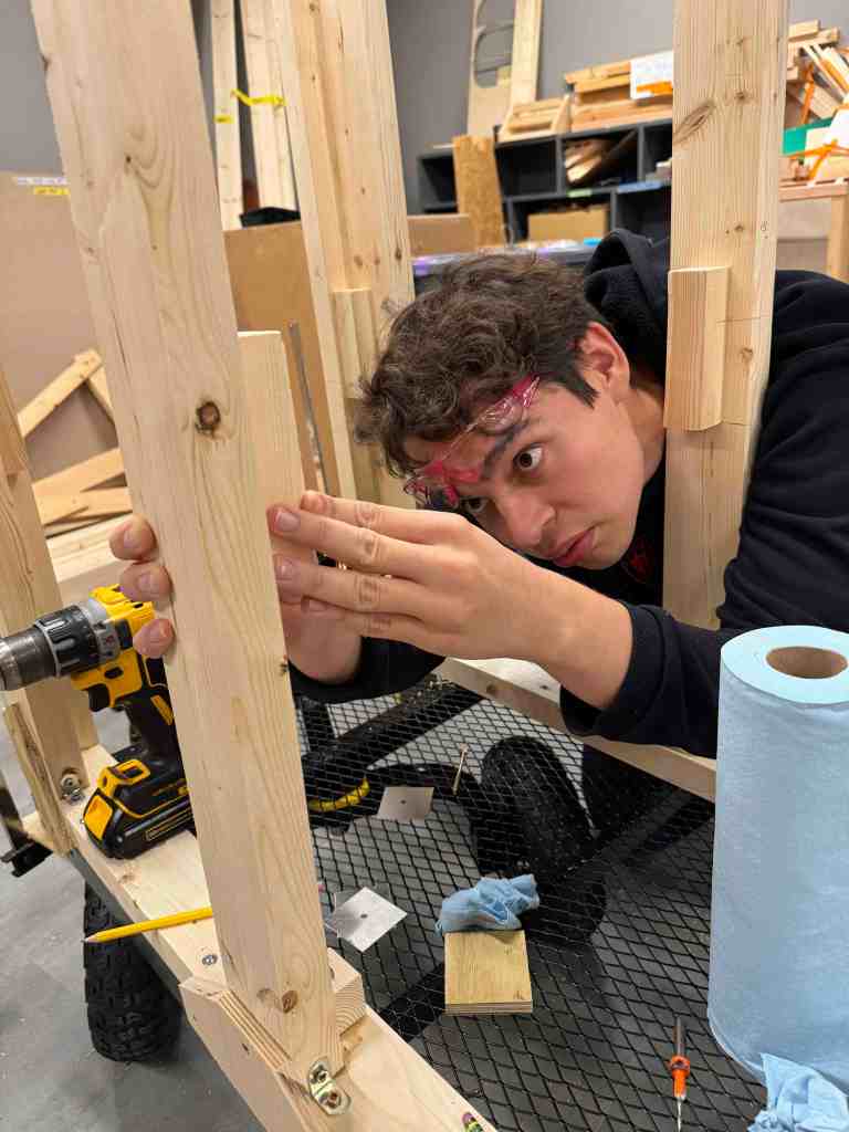
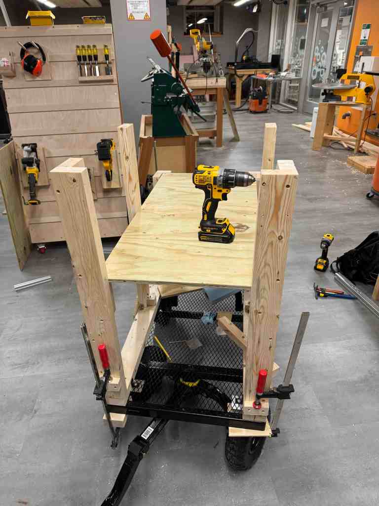
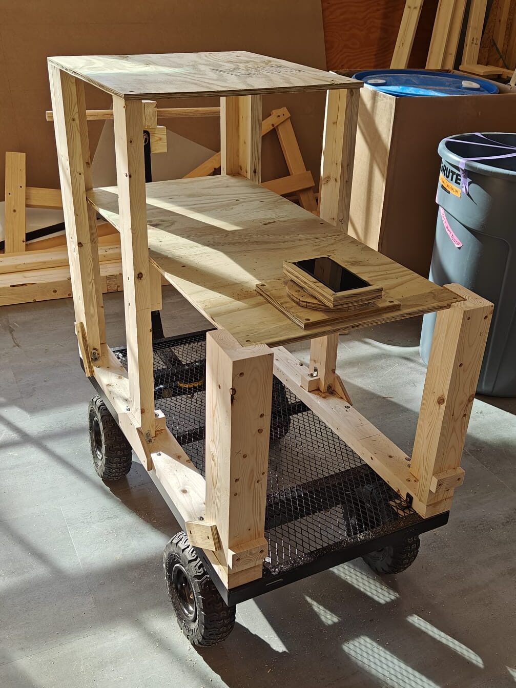
The most difficult aspect was the interface between the wood frame and the steel base. We drilled through the wood to fasten it to the outer solid lips of the base and to the inner mesh using L-brackets. The frame fabrication was otherwise quite straight forward, and just involved a lot of glueing, clamping, and screwing.
I was quite happy with the final result. We made a very rigid frame that was rigidly attached to the base. The only play we experienced when pushing the cart was from the wheels, which was out of our control.
Testing
To test the cart, we 3D printed a phone mount to record video and IMU data while pushing the cart.

Here is a video we recorded using the mount pushing over a relatively smooth road. My phone has built-in video stabilization, so it looks more stable than it actually is. Still, the vibrations weren’t too bad, but also not ideal.
The IMU data showed a similar story. So we knew that vibrations were something we wanted to improve on for the second prototype.
Prototype 2
We learned a lot through the process of making the first prototype. We wanted to make a cart that was smaller, stronger, lighter, easier to push, and that had fewer vibrations.
Design
Aluminum 8020 t-slot was an obvious choice due to its light weight, strength, and flexibility. The school had also bought a bunch of 20mmx20mm profiles which made it the most convenient option.
One of the issues we faced with prototype 1 was how difficult it was to push. We addressed this by using thinner, larger 14″ wheels and a single 8″ front swivel caster, inspired by jogging stroller designs. We figured it was a similar use case to our own.
Below you can see the jogging stroller we based our design off of, and the evolution of the cart design from first to final iteration. I designed the frame using the Onshape frame tool, which made it easy to plan out how the connections between the pieces would work.


In terms of changes between the first (middle photo) and final (last photo) iterations:
- Initially we kept a third tier to cover the laptop, but we realized it wasn’t that necessary since we could protect the laptop by storing it on the bottom tier with only a minor sacrifice to convenience.
- We swapped the plate-mounted caster with a side-mounted caster which made it easier to mount the caster such that the cart would be parallel to the ground. It also had the additional benefit of coming with a spring suspension.
- We replaced the angled front section with a rectangular front section since we could only make 90° 8020 connections with what we had on hand. It also made it easier to mount the front caster and store the battery.
We also added many more details and components that were lacking in the first iteration:
- For the handle we opted for an adjustable design where the handle could slide up and down relative to the back of the frame.
- For the paneling we opted for polycarbonate as it’s strong, lightweight, weather resistant, easy to machine, and has the added benefit of being clear.
I set up a FEA simulation with an 100 lbf loading to verify that polycarbonate was a suitable panel material.

Fabrication
I mainly handled the fabrication of the frame and wheel assembly. Below you can see photos from the process of constructing the frame. The Onshape frame tool has a built-in cut list feature which made it a breeze to know the quantity and lengths of each piece we needed to cut.


Next was the fabrication of the aluminum blocks that rigidly mount the axle to the frame. I gained some great experience using the mill, such as how to precisely place features using the DRO.


The last step was cutting and threading the axle, and putting the frame, rear wheels, front wheel, handle, polycarbonate, lidar, and camera all together!


Results
The cart we made is durable, rolls super smoothly, and otherwise meets all the requirements we set out to fulfill, especially in comparison to the first prototype.
After finishing prototype 2 we put the two prototypes to the test by once again collecting data with our 3D-printed phone mount to characterize the vibrations. Below you can see angular velocity of the 3 axes for the first (red) and second (blue) prototypes over bumpy and smooth terrain. For all axes and across both terrains you can see a marked improvement in vibration reduction from P1 to P2.

Below is the 45-page final report we submitted detailing the entire design process, as well as a short video we made summarizing key features of the design. The appendix of the report includes the BOM and technical drawings (including exploded view) I created for every part of the device.
Further Improvements
There is an issue with caster flutter on the front wheel at high speeds but this could be easily addressed by swapping out the wheel with a caster designed for higher speeds.
More side panelling can be added to improve weather protection.
