Project summary
As co-mechanical lead of the Tufts Solar Vehicle Project, I co-designed and built a 3.3’x1.7’x11′ negative mold for our carbon fiber chassis. The process from start to finish consists of:
- Constructing a frame out of 1/2″ MDF pieces
- Cutting and bonding polyurethane foam to the frame
- Sending the combined frame+foam to a CNC shop
- Machining out the shape of the chassis
- Laying up and infusing carbon fiber to produce the chassis
Background
Our chassis is a carbon-fiber monocoque design, wherein most of the tensile and compressive loads are carried parallel to the walls of the chassis (carbon fiber is much stronger in-plane than normal to the plane). A carbon fiber chassis is much lighter than the steel space-frame chassis commonly used by formula student teams (crucial for decreasing rolling resistance in a car that only runs on ~1000W of sun power), though it is much more time-consuming and expensive to manufacture.


Design Overview
Below is a view of the chassis design itself as well as the mold.


A few observations:
- The mold is flipped from the chassis, meaning the bottom surface of the mold forms the top surface of the chassis.
- The bottom surface of the chassis (what the driver sits on) is thus not technically included in the part made by the chassis mold. Instead the bottom surface of the chassis is actually the bottom surface of the aeroshell which the chassis sits on top of.
- The openings that allow the driver to enter the chassis will need to be cut in post processing, and the ribs will also need to be cut from a large 4×8′ sheet and bonded to the sides of the chassis.
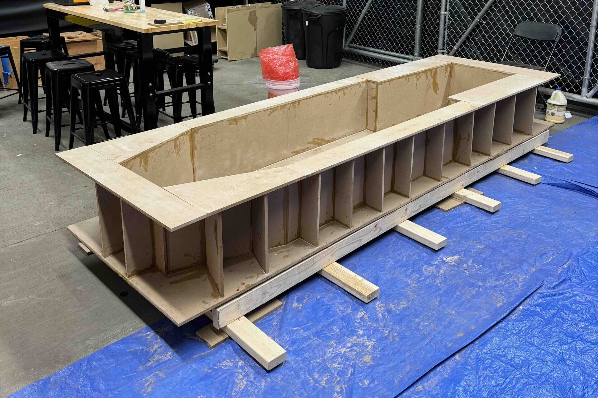
Mold Frame Design
Since machining the mold out of a huge, solid piece of tooling foam is unpractical for many reasons, we opted instead to make a frame made of MDF to support many small pieces of foam that would be bonded together and machined to form the mold surface:

Fabrication Process
The first step was to cut the MDF pieces and glue them together.


The next step was to screw some 2×4″s underneath to make it transportable, add walls for further integrity, and finally cut and bond the foam to the frame.


Then we were ready to transport it to the CNC shop in Rhode Island!


After transporting the chassis mold to Rhode Island, we waited for a few week before both the chassis and lower aeroshell molds were ready. Then we went on another road trip to pick both of them up! We had to rent a 15′ and 26′ truck for the the chassis (11′ long) and lower shell (19′ long), respectively.


From left-right, top-bottom:
- Custom casters we made to attach to the steel frame of the lower shell mold
- The trucks ready for pickup at Rhode Island
- The fully machined chassis mold
- Unloading the chassis mold at Tufts
- Unloading the lower shell mold at Tufts
- The chassis and lower shell molds safely sitting in our garage
Now all that’s left is some mold prep before doing a resin infusion and producing the carbon fiber part!